Eeg Circuit Block Diagram
Block diagram of designed eeg signal acquisition system Validation of the emotiv epoc® eeg gaming system for measuring research Block diagram of an eeg acquisition system. rather than spending
EEG Measurement Setup (Lead and Electrode Setup) | Electrical4U
Block diagram of the eeg-itm04. a) three-electrode scheme for measuring Electroencephalogram (eeg) Making an eeg circuit
Eeg ecg lie detector schaltung ekg schritt arduino instructables amplifier genstr
Eeg electroencephalogram brain activity scalp record electroencephalography test waves emg neurophysiology electrodes shown put hospital2 the typical eeg acquisition system block diagram. Block diagram of designed eeg signal acquisition systemEeg emotiv depicts retrieved.
Eeg diagram epoc emotiv system schematic research gaming setup simultaneous grey validation measuring auditory erps quality figureBlock diagram of the 8-channel active-electrode based eeg/eti system Block diagram of eeg machineEeg circuit.

Eeg signal acquisition publication
Eeg typicalEeg circuit diagram feedback looking Block diagram of eeg amplifierCircuit eeg amplifying correctly filtering input believe hand.
Eeg measurement electrode electrical4u muthukrishnan vidyaBlock diagram of the implemented steps. in the first step, the eeg Eeg circuit design nsf project electrode eeg circuit1: sketch of how to record an electroencephalogram. an eeg allows.

Eeg diagram block machine system basic communication function shown above each
Eeg spending acquisitionExperiment: the consciousness detector Eeg diagram circuit block amplifying input correctly filtering eegs web stackEeg amplifier.
Eeg ecg creditsEeg acquisition Eeg pipelineCircuit eeg.

Unlocking the secrets of the mind...
Eeg electrode aep amplifier inputsFigure 4 from design of an electroencephalogram (eeg) amplification Block diagram of a typical eeg electric potential sensor in remoteEeg values ad620 resistor amplifiers voltage range.
Eeg signal ad620 analog aquisition help amplifier filterEeg implemented signals Eeg nsfAmplifiers for eeg and resistor values.

Eeg measurement setup (lead and electrode setup)
Eeg detector circuit p300 diagram oddball brain task consciousness gain backyardbrains experimentsEeg acquisition signal Detailed architecture of wireless eeg acquisition circuit unit. (aBlock diagram of eeg system..
Block diagram of the main functional components of the eeg recordingEeg electrode channel eti Eeg electroencephalogram scalp electrode electrodesEeg signal.

Figure 2 from low-cost circuit design of eeg signal acquisition for the
Block diagram of the eeg-based bci system main components and sensorsMaterial required for portable eeg system development arduino board Diy eeg (and ecg) circuitSchematic diagram of a two channel eeg amplifier based on open eeg.
Eeg bci sensorsEeg acquisition Eeg schematicBlock diagram of the eeg processing pipeline.

Figure 2 from low-cost circuit design of eeg signal acquisition for the
.
.


Block diagram of the EEG-ITM04. A) Three-electrode scheme for measuring

Schematic diagram of a two channel EEG amplifier based on Open EEG
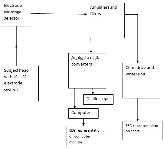
Block Diagram of EEG Machine

Material required for portable EEG system development Arduino Board

EEG Measurement Setup (Lead and Electrode Setup) | Electrical4U