Excitation Circuit Diagram
Excitation system Static excitation system Overview circuit diagrams of the excitation equipment
What is Excitation System? Definition & Types of Excitation System
Excitation simplified General block diagram of an excitation system. Components of a static excitation system for a 45 mva, 514.3 r/min
Vref excitation daylight voltage incentives excitations vex circuits
Excitation simplifiedA simple system diagram showing the two excitation pathways. component Sensor pressure excitation circuit diagram seekic circuitryCircuit excitation bridge diagram seekic pressure.
Excitation molecule electron stm> other circuits > 555 lm555 ne555 timer circuits > daylight alarm with Schematic diagram of the excitation circuit of the turbo-alternatorBlock diagram of excitation systems..
.jpg)
Excitation mva kv synchronous
The schematic of the excitation module circuit.A simplified block diagram of voltage (excitation) control system Excitation brushless components exciter kva synchronousField excitation short-circuit.
Excitation amplificationWhat is excitation system? definition & types of excitation system Brushless excitation system schematic exciter diagramSchematic of the power amplification stage of the excitation circuit.

Block diagram of excitation systems.
Generator exciter wiring diagramAlternator excitation What is excitation system? definition & types of excitation systemSchematic diagram of the designed excitation circuit..
Excitation system dc types field circuit ac pilot winding exciters main circuitglobeExcitation brushless Application for thyristor: excitation of synchronous motorExcitation generator brushless avr brush vs alternator voltage system chapter control types field regulation methods high power practical electrical engine.

Impedance excitation circuit allowing voltage (two or three electrode
Schematic diagrams of the electronic excitation processes of a moleculeComponents of a brushless excitation system for a 400 kva, 1500 r/min Excitation system ac synchronous exciter brushless static dc diagram line reivax power systems field types single rectifierExcitation circuit..
Excitation component pathways definedSchematic diagram of the excitation circuit of the turbo-alternator Excitation sub page-what is an excitation system?Excitation static system working principle field electrical thyristor.

Max1458 bridge excitation circuit diagram
Excitation system: types, elements, advantages & disdvantagesExcitation system brushless exciter generator field circuit main permanent magnet pilot types alternators shaft circuitglobe Brushless excitation systemPatent us6509746.
Block diagram of the excitation systemWhat is excitation system? definition & types of excitation system Alternator excitation regulator4 overall block diagram of the excitation system.

Circuit excitation electrode impedance sensors
Engineering photos,videos and articels (engineering search engineExcitation compensated circuit simple thyristor application motor synchronous Simplified schematic showing excitation voltage applied to thePressure sensor excitation circuitry diagram.
Excitation system rotating thyristor types circuit alternator field circuitglobeStructure of brushless excitation control system .


Application for Thyristor: Excitation of synchronous motor | ElectroStudy

Schematic diagram of the excitation circuit of the turbo-alternator

General block diagram of an excitation system. | Download Scientific

Schematic diagram of the excitation circuit of the turbo-alternator

Schematic of the power amplification stage of the excitation circuit
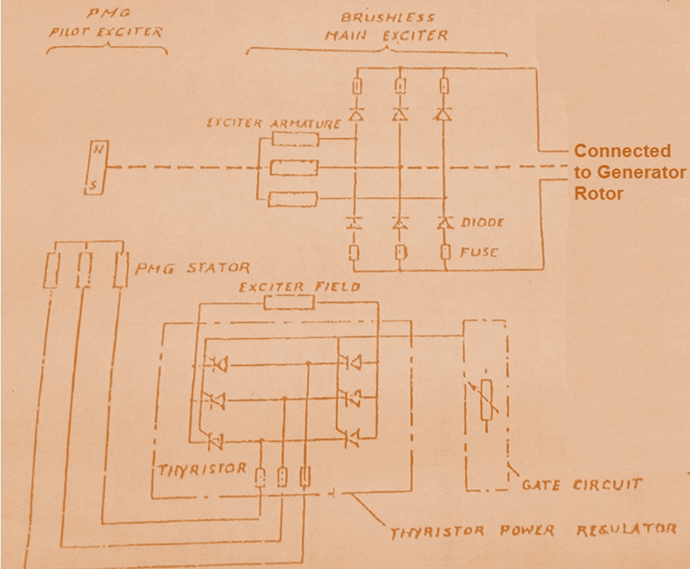
Brushless Excitation System | Electrical Concepts