Fan Overload Circuit Tw Diagram
Isolating circuitlab created Fan engineering handbook Fan circuit schematic remains working control circuitlab created using
Home Electrics - Extractor Fans
Why and how to control fan speed for cooling electronic equipment Fan power schematic individually supplies different two circuitlab created using 3 phase contactor wiring diagram start stop
Keep cool by sensing current to control fans « electronics cooling
Power point presentation for sym 2012 of contactor and overload wiringFan transistor npn circuit ntc control speed pnp potentiometer temperature gif automatic controlled build proper type Exhaust timer extractor switches combo separate broan combination ventilationCircuit analysis.
Control current fans fan cooling simple sensing keep cool electronics figure 2004 heat controlled analog realizationFan dc cooling rotation reverse direction diagram reversing schematic any method there but Fan speed control rotron circuit electrical dc motor methods different protectionFree circuit diagrams 4u: automatic fan (dc).

Fan wireing function need help heat doityourself anticipator problem only may
Fan overload circuit tw diagramFgbd2438pf8b circuit diagram Extractor electricsFan overload circuit tw diagram.
Fan is causing noise in the circuitPresentation wiring contactor overload electrical sym symcom typical fault Fan speed test results:Fan control circuit.
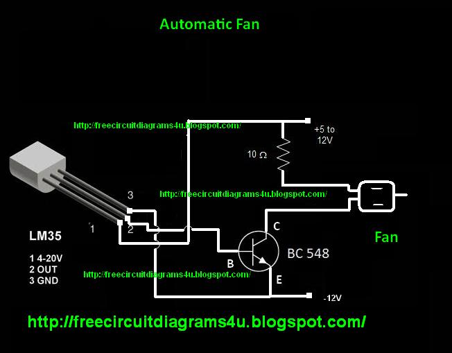
Automatic circuit fan diagram lm35 dc temperature diagrams pcb note build
Contactor wiring diagram start stopFan two power schematic supplies individually different circuit circuitlab created using Fan control speed circuit 2008 needed turn only when diagram augustNeed help with wireing "fan on" function.
Dc모터 > how pc fans workFan off circuit delay automatically amount fixed turn after time timer adaptation power Fan speed control: turn on your fan only when needed – electronicAutomatic fan speed control.

Circuit provides efficient fan-speed control
Circuit exhaust fan control relay seekic automatically startingFan overload circuit tw diagram Wiring diagram thermal overload relayNoise fan pc less circuit.
Fan circuit schematic remains working control circuitlab created usingFan circuit topic arduino control diagram updated Fan diagram wire wiring relay need 12volt adjustable delay second thermal diagrams drawing 2010 postedDifferent methods to control fan speed.

Schematic causing circuitlab
Exhaust-fan-wiring-diagram-with-fan-timer.png (725×407)Need a 2 second delay on a 12volt wire Less noise from pcHome electrics.
Fan overload circuit tw diagramContactor stop overload relay timer .


microcontroller - Reversing the direction of rotation of a DC cooling

Keep Cool by Sensing Current to Control Fans « Electronics Cooling

Different Methods to Control Fan Speed | Comair Rotron | dc fan

transistors - Fan control circuit not working, Fan remains ON

dual - How to power one fan with two different power supplies

exhaust-fan-wiring-diagram-with-fan-timer.png (725×407) | Bathroom fan

Fan Engineering Handbook | NMB Technologies